
Building a Self-Balancing Kicking Robot From Scratch
Introduction
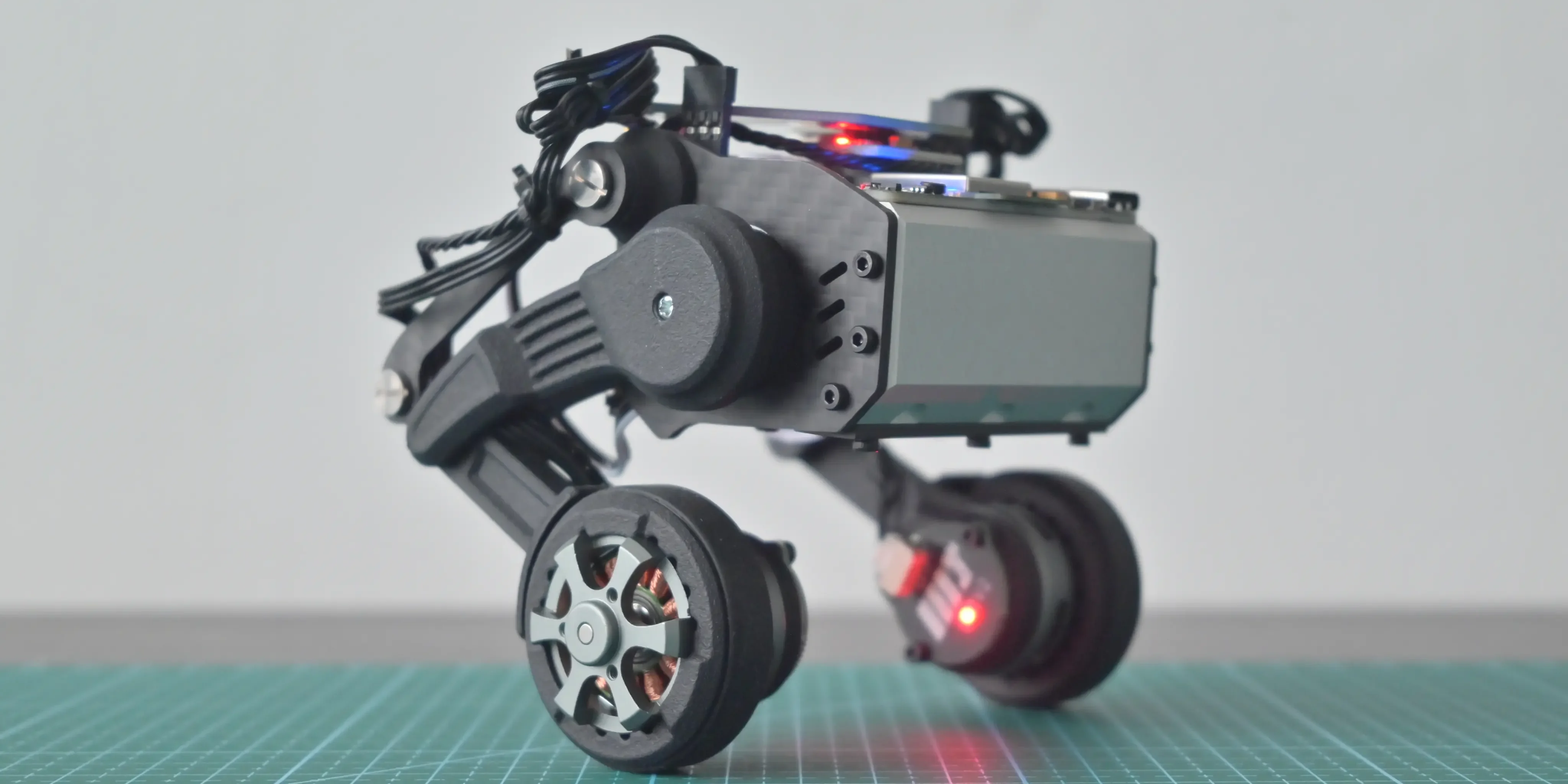
In this project, we designed and developed a powerful two-wheel self-balancing robot capable of:
- Dynamic balancing using inverted pendulum control
- Real-time PID stabilization
- Ball detection using camera vision
- Kicking mechanism using high torque servo
- Encoder-based motor feedback
- Future ROS2 and AI compatibility
This project combines multiple robotics engineering domains:
- Embedded systems
- Control systems
- Power electronics
- Sensor fusion
- Computer vision
- Mechanical design
- Real-time robotics control
Final Robot Architecture
                CAMERA
                   |
            Raspberry Pi 4
                   |
            Serial Communication
                   |
             Arduino UNO
           /              \
      BNO085 IMU      Servo Control
           |                |
     PID Controller      Kicking Leg
           |
      BTS7960 Driver
           |
      Encoder Motors
           |
         Wheels
Understanding Self Balancing Robots
A self-balancing robot is fundamentally an:
Inverted Pendulum System
An inverted pendulum is naturally unstable.
If the robot tilts slightly forward:
- Gravity increases the tilt
- The robot begins falling
- Controller detects angle error
- Motors move wheels forward
- Center of mass realigns
- Robot balances again
This balancing loop runs hundreds of times every second.
Self Balancing Principle
         Center of Mass
                ●
               /|
              / |
             /  |
            /   |
           /    |
          /     |
         /      |
        O-------O
          Wheels
The controller continuously moves the wheels under the center of mass.
Core Hardware Components
| Component | Purpose | |---|---| | Rhino 100RPM Encoder Motors | Wheel actuation | | BTS7960 Driver | High-current motor control | | BNO080/BNO085 | Orientation sensing | | Arduino UNO | Real-time balancing controller | | Raspberry Pi 4 | Vision processing | | OT5325M Servo | Ball kicking mechanism | | XL4015 Buck Converter | Voltage regulation | | 3S Li-ion Battery | Main power source |
Motor Selection Engineering
Motor selection was the most critical design decision.
Initially considered:
- JGB37 motors
- N20 motors
- Generic DC gear motors
However, these motors lacked sufficient torque for:
- balancing corrections
- payload handling
- fast recovery
- future scalability
Final selection:
Rhino 100RPM 25kgcm Planetary Encoder Motor
Why These Motors?
- High torque output
- Planetary gearbox
- Encoder feedback
- Excellent stability
- Future AI robot scalability
Why Planetary Gearbox?
Compared to normal spur gearboxes:
- Higher efficiency
- Lower backlash
- Better torque transfer
- Longer durability
- Better disturbance handling
Why 100RPM?
Motor RPM directly affects balancing behavior.
If RPM is too low:
- Sluggish correction
- Delayed balancing
- Weak recovery
If RPM is too high:
- Oscillation
- Instability
- Difficult PID tuning
100RPM created the best balance between:
- speed
- stability
- correction torque
Encoder Importance
Encoders provide:
- wheel speed feedback
- odometry
- motion estimation
- disturbance rejection
- future autonomous navigation capability
Without encoders:
- balancing becomes unstable
- motion estimation becomes inaccurate
- control quality decreases significantly
Motor Driver Selection
The selected driver:
BTS7960 High Current Driver
Why BTS7960?
Balancing robots generate large current spikes during:
- startup
- rapid correction
- disturbance recovery
- sudden direction reversal
Advantages:
- high current capability
- reliable PWM control
- stable motor driving
- future scalability
IMU Selection
The robot requires highly accurate orientation sensing.
Initially considered:
- MPU6050
Final selection:
BNO080 / BNO085
Why BNO085?
- Built-in sensor fusion
- Cleaner orientation estimation
- Lower drift
- Better noise filtering
- Higher balancing stability
Why IMU Quality Matters
Poor IMU data causes:
- oscillation
- delayed correction
- instability
- jitter
- balance failure
Balancing quality depends heavily on:
- sensor latency
- angle accuracy
- noise reduction
- update frequency
Control System Architecture
The robot uses a dual-controller architecture.
Arduino UNO Responsibilities
- IMU reading
- PID calculations
- motor PWM generation
- balancing loop
- servo control
Raspberry Pi 4 Responsibilities
- camera processing
- object detection
- AI vision experiments
- future ROS2 integration
System Communication Architecture
 Raspberry Pi 4
       |
 USB Serial Communication
       |
 Arduino UNO
       |
  PID Controller
       |
  BTS7960 Driver
       |
 Encoder Motors
PID Control System
The balancing controller uses PID control.
PID Equation
- P → proportional correction
- I → accumulated error correction
- D → damping and prediction
PID Responsibilities
| PID Term | Purpose | |---|---| | P | Immediate correction | | I | Long-term drift correction | | D | Oscillation damping |
Real-Time Balancing Loop
Read IMU Angle
      ↓
Calculate Error
      ↓
Run PID Controller
      ↓
Generate PWM
      ↓
Drive Motors
      ↓
Robot Corrects Tilt
      ↓
Repeat
Kicking Mechanism
The robot includes a high-torque kicking system using:
OT5325M 25kg Servo
Servo Responsibilities
- kick motion
- leg actuation
- fast directional movement
Why High Torque Servo?
The kicking mechanism generates large impulse forces.
Low torque servos:
- stall easily
- respond slowly
- cannot deliver strong kicks
Power System Design
The robot uses:
- 3S Li-ion battery
- XL4015 buck converter
- separated logic and motor power paths
Why Power Design Matters
Motor current spikes can create:
- voltage drops
- Arduino resets
- sensor instability
- balancing failure
Proper power regulation is critical.
Battery Architecture
3S Li-ion Battery
        |
   Main Power Rail
      /      \
Motor Power   Buck Converter
    |               |
BTS7960        Arduino + Sensors
Mechanical Design Considerations
Key balancing factors:
- center of mass height
- wheel spacing
- frame rigidity
- motor alignment
- weight distribution
Important Design Rule
A lower center of mass improves stability.
Challenges Faced During Development
Oscillation Problems
Caused by:
- excessive PID gains
- noisy IMU data
- unstable motor response
Power Noise
High current motors introduced electrical noise into the control system.
Mechanical Instability
Frame vibration affected IMU accuracy.
Future Improvements
Planned upgrades:
- ROS2 integration
- SLAM
- autonomous navigation
- reinforcement learning
- AI object tracking
- computer vision pipelines
- obstacle avoidance
Why This Project Matters
This project creates a powerful foundation for learning:
- robotics engineering
- embedded systems
- control theory
- real-time systems
- robotics AI
- sensor fusion
- autonomous robotics
This is not just a beginner robot.
It is a scalable robotics engineering platform.
Robotics Concepts Learned
This project teaches:
- PID control
- embedded programming
- motor drivers
- IMU integration
- robotics mathematics
- balancing systems
- real-time control
- robotics architecture
Final Thoughts
Building a self-balancing robot is one of the best ways to deeply understand robotics engineering.
This project combines:
- hardware
- software
- mechanics
- control systems
- electronics
- AI foundations
into one complete robotics platform.
The lessons learned from this robot directly apply to:
- humanoid robots
- autonomous robots
- industrial robotics
- AI robotics systems
- advanced motion control systems
Next Steps
Future articles will cover:
- PID tuning in detail
- Kalman filters
- encoder mathematics
- balancing equations
- ROS2 integration
- computer vision pipeline
- robotics AI architecture
- autonomous navigation
Frequently Asked Questions
Become a Software Robotics Engineer
Robotics Engineering is one of the most exciting fields in modern technology. Start with small projects, stay consistent, build practical robotics systems, and continuously improve your engineering and problem-solving skills. Every advanced robotics engineer once started with their first Arduino project, first motor driver, and first balancing robot.